
DapuStor NVMe FDP Deep Dive: From Concept to Real-World Deployment
In enterprise storage, balancing SSD endurance with sustained high performance amidst surging write workloads remains a critical challenge. The NVMe Flexible Data Placement (FDP) specification emerged precisely to resolve this bottleneck. As an experienced innovator in enterprise storage, DapuStor has transitioned FDP from theoretical research to robust engineering implementation. Today, its latest generation Gen5 QLC SSDs and H5/R6 TLC SSDs fully support standard NVMe FDP features, delivering a future-ready storage foundation.

DapuStor QLC & TLC SSDs: Fully FDP-Enabled
The advent of NVMe FDP introduces a standardized paradigm for mitigating write amplification in enterprise storage environments. By effectively reducing the Write Amplification, it significantly extends SSD endurance while securing consistent, long-term Quality of Service (QoS). This comprehensive guide dissects FDP technology from the ground up, covering its architectural rationale, protocol specifications, deployment best practices, and development interfaces.
01 The Context: Write Amplification & The FDP Solution
Write Amplification is an intrinsic characteristic of SSD architecture. It refers to the discrepancy where the actual amount of data committed to the NAND flash media exceeds the amount of data originally written by the host. This phenomenon directly compromises SSD endurance and throttles performance.
The Root Cause: Garbage Collection
The primary driver of Write Amplification is the SSD's Garbage Collection (GC) mechanism. Due to the physical constraints of NAND Flash, data must be erased at the block level, even though it is written at a much smaller granularity. Consequently, a block targeted for erasure often contains a mix of invalid data (ready to be deleted) and valid data (must be kept). To erase the block, the controller must first read and migrate the valid data to a new block. This redundant data migration is the source of Write Amplification.
The FDP Solution: Lifecycle-Aware Placement
Industry research confirms that segregating data based on its lifecycle patterns into distinct physical regions can drastically mitigate Write Amplification. For example:
• Strategy: Segregate frequently updated (Hot) data from static (Cold) data.
• Impact: This ensures that data residing in the same physical block invalidates synchronously. When a block is triggered for erasure, the majority of its data is already invalid, significantly minimizing the need to migrate valid data. The result is a significantly lower Write Amplification Factor (WAF).
02 NVMe Specification Support: The Architectural Framework
Achieving physical isolation based on data lifecycles requires a synergistic orchestration between the Host and the SSD:
• Host-Side Responsibility: Categorizing data payloads based on lifecycle patterns (e.g., distinguishing high-churn "Hot" data from static "Cold" archives).
• SSD-Side Execution: Partitioning discrete physical regions to physically isolate these differentiated data streams.
The NVMe FDP specification establishes a robust taxonomy to govern this mechanism and provide the host with methods to map data to specific physical zones:
• Reclaim Unit (RU): The fundamental physical storage region managed internally by the SSD, comprising a specific set of NAND flash blocks.
• Reclaim Unit Handle (RUH): An index pointing to a specific RU. Crucially, the mapping between an RUH and an actual RU is virtualized by the SSD and opaque to the host. This abstraction layer decouples host operations from internal SSD resource scheduling, optimizing overall efficiency.
• Reclaim Group (RG): A logical collection of RUHs. Most current enterprise SSD implementations use a single Reclaim Group structure.
• Placement Handle (PH): The host-facing reference handle used to target a specific RUH. Within a given Namespace, there is a direct 1:1 mapping between a PH and an RUH.
The Workflow: Leveraging this architecture, the host tags each write command with a specific Placement Handle based on the data's classification. Upon receipt, the SSD controller parses this tag, triggering a multi-tier mapping sequence: Placement Handle (PH) → Reclaim Unit Handle (RUH) → Reclaim Unit (RU). This ensures the data is committed precisely to its designated physical zone.
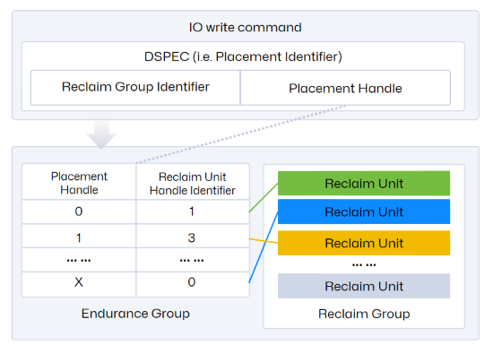
As visualized in the diagram, the Reclaim Group is nested within the Endurance Group. Typically, an NVMe SSD features a single Endurance Group, yet it supports the provisioning of multiple Namespaces within that same group.
Note that configuring FDP requires nvme-cli version 2.3 or higher.
03 Configuration & Enablement of FDP
Retrieving Available FDP Configuration Profiles
Configuring FDP requires selecting a pre-validated configuration profile (rather than manually tuning individual FDP parameters). Administrators can query the supported configuration indices using the command below. The following output example illustrates a typical valid profile.
nvme fdp configs /dev/nvme1 -e 1
FDP Attributes: 0x80
Vendor Specific Size: 0
Number of Reclaim Groups: 1
Number of Reclaim Unit Handles: 8
Number of Namespaces Supported: 128
Reclaim Unit Nominal Size: 9873653760
Estimated Reclaim Unit Time Limit: 345600
Reclaim Unit Handle List:
[0]: Persistently Isolated
[1]: Persistently Isolated
[2]: Persistently Isolated
[3]: Persistently Isolated
[4]: Persistently Isolated
[5]: Persistently Isolated
[6]: Persistently Isolated
[7]: Persistently Isolated
Analysis of this Configuration Schema: In this specific profile, the resources are provisioned as follows:
• Reclaim Groups: 1 allocated
• Reclaim Unit Handles (RUHs): 8 available for mapping
• Namespace Support: Up to 128 supported Namespaces within the Endurance Group
Effective Scope & Initialization
• Scope of Application: FDP enablement operates at the Endurance Group level, creating a global policy that cascades to all Namespaces within that group.
• Critical Prerequisite: Before activating FDP, the drive must be returned to a clean state. It is recommended to delete all existing Namespaces prior to configuration. Once enabled, any newly provisioned Namespaces will automatically inherit FDP attributes.
• Command Example: The following nvme-cli command demonstrates the enablement process:
nvme set-feature /dev/nvme1 -f 0x1d --value 1 -c 0x201 -s
Syntax Breakdown:
• -f 0x1d: Specifies the Feature Identifier (FID) for FDP (0x1d).
• -c 0x201: Defines the content of DWORD 12 in the NVMe command structure. According to the NVMe Specification:
The 0x2 value selects the FDP Configuration Profile at Index 2 (referencing the Configuration Index, 0-based).
The 0x01 bit sets the FDP Enable flag to "On".
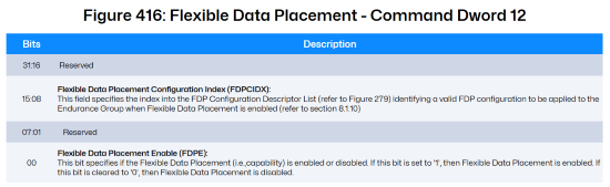
*Image Source: [1] NVM-Express-Base-Specification-Revision-2.1
Allocating Physical Placement Zones
Provisioning & Mapping: The final step involves provisioning a Namespace and establishing the mapping relationship between the Placement Handle (PH) and the Reclaim Unit Handle (RUH).
nvme create-ns /dev/nvme1 -c 0x1bf1f72b0 -s 0x1bf1f72b0 -f 0 -d 0 -e 1 -m 0 -n 2 -p 2,5
Syntax Breakdown:
• -f 0: LBA Format Index. Value 0 selects the drive's primary supported format (e.g., 1 LBA maps to a 512-byte physical block).
• -c -s: Capacity & Size. The hexadecimal values define the Namespace capacity in total data blocks (block size is determined by the -f parameter).
• -n 2: Placement Handle Count. Specifies that this Namespace will utilize 2 Placement Handles (implying the allocation of 2 distinct RUHs).
• -p 2,5: PH-to-RUH Mapping Schema. This string defines which RUHs are assigned.
Logic: 2,5 maps to RUH 2 and RUH 5 respectively.
Important Note (Implicit Indexing): The command accepts only the list of RUH IDs. The corresponding Placement Handle IDs are assigned implicitly and sequentially starting from 0.
Result: Placement Handle 0 → RUH 2; Placement Handle 1 → RUH 5.
Configuring the Directive Feature
The Role of DSPEC & Directives: As illustrated, the DSPEC field embedded within the Host's write command serves as the navigational signal, guiding the SSD's internal data placement logic. This signaling mechanism relies entirely on the NVMe Directives framework. Consequently, configuring the Directive feature is a mandatory prerequisite for operationalizing FDP.
The Directive Protocol: NVMe Directives provide a robust protocol for configuration exchange between the Host and the SSD.
• Taxonomy: The specification defines four Directive types: Identify, Streams, Data Placement, and Vendor Specific.
• Transport Mechanism: Interaction is bidirectional, utilizing Directive Send (Host-to-Device configuration) and Directive Receive (Device-to-Host status reporting).
• FDP Implementation: In the context of FDP, the system leverages the Data Placement Directive type. The Host issues a Directive Send command to explicitly enable this Data Placement capability on the drive.
Command Example: The following command activates the Directive functionality:
nvme dir-send /dev/nvme1n1 -n 1 -D 0 -O 1 -T 2 -e 1 -H
Syntax Breakdown:
• dir-send: Specifies the Directive Send opcode.
• -n 1: Targets Namespace ID 1.
• -T 2: Selects Directive Type 2 (The specific identifier for the Data Placement directive)
• -e 1: Enable Flag. Sets the status of the selected Directive (Data Placement) to "Enabled".
04 Executing Lifecycle-Based Writes
Operational Workflow: Post-initialization, the Host can execute standard NVMe Write operations with an embedded Placement Handle. This directive instructs the SSD to physically segregate the incoming data into specific zones based on its assigned lifecycle category.
Protocol Implementation: According to the NVMe Command Set specification, this logic is enforced via specific bit-fields within the Write Command structure:
• Command Dword 12 (Bits 23:20): Specifies the Directive Type. This must be set to indicate Data Placement.
• Command Dword 13 (Bits 31:16): Houses the DSPEC (Directive Specific) field. This is the container where the Host populates the target Placement Handle value.
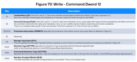
*Image Source: [2] NVM Express NVM Command Set Specification, Revision 1.2
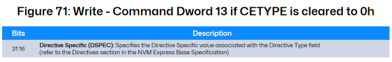
*Image Source: [2] NVM Express NVM Command Set Specification, Revision 1.2
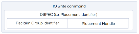
Deployment Norm: Per the NVMe Base Specification, common enterprise SSD deployments typically utilize a single Reclaim Group architecture. Consequently, the Placement Handle is commonly specified using the format illustrated below:
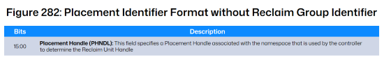
*Image Source: [1] NVM-Express-Base-Specification-Revision-2.1
05 Telemetry, Monitoring, and Event Debugging
Acquiring FDP Telemetry
The NVMe Specification standardizes the I/O Management Receive command as the primary mechanism for the Host to query drive operational metrics.
In an FDP context, this command is utilized to retrieve the Reclaim Unit Handle Status (the statistics of the RU currently mapped to an RUH). This is achieved by setting Command Dword 10 (Bits 07:00) to a value of 0x01.
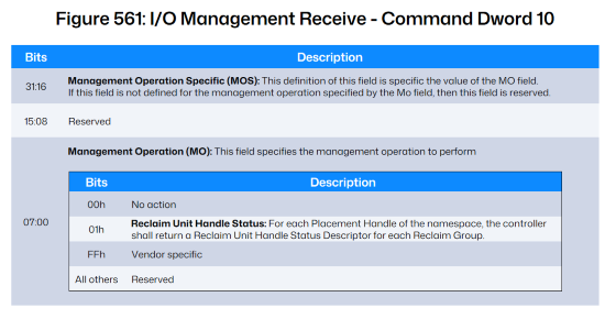
*Image Source: [1] NVM Express Base Specification, Revision 2.1
Key Metrics Breakdown: Per the NVMe Command Set Specification, the returned data structure reports the following critical fields:
• Placement Identifier: The specific ID corresponding to the Host-side Placement Handle.
• Reclaim Unit Handle Identifier: The internal ID assigned to the RUH by the SSD.
• Estimated Active Reclaim Unit Time Remaining (EARUTR): A predictive metric indicating the remaining write time for the active RU. Note: Upon expiration, the RUH will automatically transition to a fresh RU.
• Reclaim Unit Available Media Writes (RUAMW): The remaining capacity within the active RU, quantified as the number of available logical blocks.
Command Example: The following command retrieves the FDP statistical report:
nvme fdp status /dev/nvme1n1
Placement Identifier 0; Reclaim Unit Handle Identifier 2
Estimated Active Reclaim Unit Time Remaining (EARUTR): 345600
Reclaim Unit Available Media Writes (RUAMW): 19284480
Placement Identifier 1; Reclaim Unit Handle Identifier 5
Estimated Active Reclaim Unit Time Remaining (EARUTR): 345600
Reclaim Unit Available Media Writes (RUAMW): 19284480
Event Monitoring & Diagnostic Logging
The Diagnostic Framework: NVMe FDP incorporates a robust Event Notification Mechanism designed to capture I/O errors and track specific operational anomalies during read/write cycles. This telemetry is critical for application debugging and system optimization. Once event monitoring is configured, administrators can retrieve detailed FDP-specific reports via the standard NVMe Log Page 0x23.
(1) Activating Event Triggers
To leverage this mechanism, specific FDP events must first be enabled.
Command Example:
nvme fdp set-events /dev/nvme1 -n 1 -e 1 -p 0 -t 0,3
# Output: set-events: Success
Syntax Breakdown:
• -p 0: Targets Placement Handle 0.
• -t 0,3: Enables triggers for Event Types 0 and 3:
Event 0 (Reclaim Unit Not Fully Written):Indicates a Host-Initiated Transition. The Host issued a command that forced the RUH to switch to a new RU before the current RU was completely filled.
Event 3 (Invalid Placement Identifier): Indicates an Invalid Targeting Error. The Host issued a write command containing a Placement Handle ID that does not exist or is unauthorized.
(2) Verifying Active Event Policies: To audit which event types are currently enabled, use the get-feature command:
nvme get-feature /dev/nvme1n1 -f 0x1e -s 0/3 -c 0 -H
get-feature:0x1e (Flexible Direct Placement Events), Current value:0x00000002
Reclaim Unit Not Fully Written : Enabled
Invalid Placement Identifier : Enabled
Sample Output Analysis: The output confirms that the feature 0x1e (Flexible Data Placement Events) is active, with both "Reclaim Unit Not Fully Written" and "Invalid Placement Identifier" statuses set to Enabled.
(3) Retrieving Diagnostic Logs: FDP event history is archived in Log Page 0x23. The following command retrieves this log in a structured JSON format for easy parsing.
Command Example:
nvme fdp events /dev/nvme1n1 -e 1 -E -o json
{
"n":0,
"events":[]
}
• -e 1: Specifies Endurance Group 1.
• -E: Filters for Host-Event logs.
(4) Real-World Debugging Scenario
Scenario: The Host attempts to write data using a non-existent Placement Handle ID (e.g., ID 22).
Result: The system captures a Type 3 Exception. The nvme fdp events command will return a log entry similar to the following:
{
"type":3,
"fdpef":*,
"pid":22,
"timestamp":*,
"nsid":*
}
This log entry precisely pinpoints that the application incorrectly requested PID 22, allowing developers to rapidly isolate the code defect.
06 Application Integration Strategies
Applications primarily leverage FDP capabilities through two distinct implementation pathways:
Method 1: I/O Passthrough
The Challenge: Kernel Lag
In standard Linux environments, applications typically interact with SSDs indirectly via the Kernel's file system or block layer abstractions (as depicted below). However, the rapid evolution of NVMe Specifications—introducing advanced features like FDP and Key-Value (KV) sets—often outpaces native kernel support. Standard file and block interfaces currently lack the native semantics to expose these nascent features.
The Solution: io_uring Passthrough
To bridge this gap, the Linux Kernel provides the io_uring interface. This mechanism creates a high-performance conduit, allowing applications to bypass legacy abstraction layers and submit NVMe commands directly to the driver.
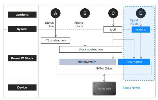
*Image source: https://www.usenix.org/conference/fast24/presentation/joshi
Implementation Guide: Leveraging liburing
Developers are advised to utilize the liburing open-source project as the reference implementation (Repository: https://github.com/axboe/liburing/tree/master).
• Reference Code: specifically, the test/io_uring_passthrough.c file serves as the definitive blueprint for invoking the I/O passthrough method.
• Code Adaptation for FDP: Developers need to modify the source code to inject FDP logic. For instance, within the __test_io function, modify the command structure to populate cmd->cdw12 and cmd->cdw13. This allows the insertion of the Placement Handle field directly into the Write Command payload.
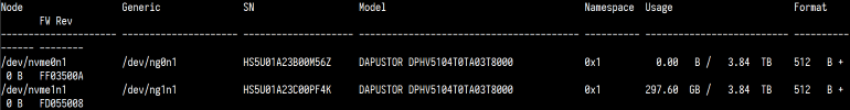
• Critical Configuration Note: When executing tests or running the application, ensure target selection uses the Character Device Node (not the Block Device). As shown in the nvme list output below, select the device path listed under the "Generic" column.
Method 2: SPDK Integration
Native Support Overview: Starting with release 23.05, the Storage Performance Development Kit (SPDK) has integrated support for NVMe FDP features.
Developer Reference: For a comprehensive reference on implementing FDP logic via SPDK APIs, developers should examine the source code located at test/nvme/fdp/fdp.c within the official repository. This file serves as the canonical example for orchestrating the following core operations:
1. Retrieving FDP Configurations: Querying valid Reclaim Groups and Placement Handle mappings.
2. Executing FDP-Enabled Writes: Submitting I/O requests with embedded Placement Handles.
3. Acquiring FDP Telemetry: Fetching detailed statistics for specific Reclaim Units.
4. Monitoring FDP Events: Polling the event log for status updates or error flags.
Validation Workflow: To validate these functions in a live environment, developers can bind an FDP-capable SSD to the SPDK driver, compile the test utility, and execute the fdp binary. The following command illustrates how to target a specific PCIe device address to observe the functional output:
./fdp -r 'trtype:PCIe traddr:0000:c8:00.0'
07 Validation Methodology
Before application development, users can validate FDP functionality using fio. Please ensure the fio version is 3.34 or higher.
For testing, you can use the examples/uring-cmd-fdp.fio file from the fio open-source project, modifying its fields according to the actual FDP configuration of the drive. Below is the content of the uring-cmd-fdp.fio file, where fdp=1 indicates enabling the FDP feature, ioengine=io_uring_cmd indicates using the I/O passthrough method, and fdp_pli represents the Placement Handle used by the fio thread's write operations, which can be modified according to the drive configuration.
[global]
filename=/dev/ng0n1
ioengine=io_uring_cmd
cmd_type=nvme
iodepth=32
bs=4K
fdp=1
time_based=1
runtime=1000
[write-heavy]
rw=randrw
rwmixwrite=90
fdp_pli=0,1,2,3
offset=0%
size=30%
[write-mid]
rw=randrw
rwmixwrite=30
fdp_pli=4,5
offset=30%
size=30%
[write-light]
rw=randrw
rwmixwrite=10
fdp_pli=6
offset=60%
size=30%
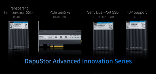
08 DapuStor: Pioneering the Frontier of NVMe Innovation
As the industry accelerates into the Petabyte-scale storage era, FDP serves as a critical solution to the write amplification bottleneck, significantly bolstering SSD stability. Spanning key innovations from FDP to Transparent Compression, DapuStor remains steadfast in its technology-driven strategy. Leveraging the flexible architecture of the advanced Gen5 controllers, DapuStor is dedicated to accelerating the translation of emerging NVMe standards into robust, production-ready engineering capabilities.
For more information, please contact:
Email: mkt@dapustor
Website: www.dapustor.com