How High-speed Secure Interoperability Interface (HSI) Increases Controller Stability
Enterprise SSDs not only require higher performance, but also have demanding stability requirements. As a professional enterprise SSD company, DapuStor has a complete quality assurance system from chip design to product development.
01 Traditional High-speed Secure Interoperability Interface (HSI)
Traditional High-speed Secure Interoperability Interface (HSI) has following drawbacks in larger modules:
1. Timing is limited by the size of the receiver module state transferlatency, so if the single clock cycle Timing requirement cannot be met, the operating frequency can only be reduced.
2. There are too many constraints on the back-end design, making iterative attempts at independent module harden and TOP PnR necessary for the back-end design.
3. For some controllerswith very high security and stability, traditional transmission methods cannot reach their requirements.

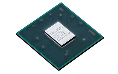
DapuStor in-house SSD controller DP600
02 DapuStor's ControllerDesign Solutions
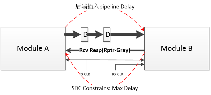
Dapustor uses the receiver to transmitthe FIFO pointer and the pointer is passed to the transmitter in Gray Code. The transmitter does not need a single clock cycle to determine whether the receiver has received the data successfully before sending it, but only needs to determine whether it can continue to send data to the receiver based on the amount of data it has sent and the current amount received by the receiver. The use of the Gray Code transmission method of the receiver is on the one hand an easy way to receive and transmit asynchronously, and on the other hand the Gray Code pointer can still be treated as asynchronous even in the synchronous clock state, with the maximum delay method set at the back end. This solves the problem of the single clock cycle requirement for state transfer from the receiver to the transmitter. Even if the FIFO pointer is delayed by several clock cycles, the communication performance is still not affected as long as the FIFO depth at the receiver is set appropriately.
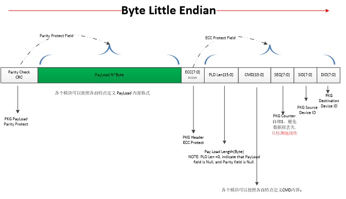
In terms of security and stability, this design uses packet-based datatransmission. A complete data transmission is divided into a packet header, a data part and a checksum part. The packet header is protected by ECC and the data part is protected by CRC; and a loss prevention and routing error check is added to the packet header.

Interconnection Structure Between Modules
The structure in the diagram above supports the processing of asynchronous clocks for transmitter module A and receiver module B. The receiving module B uses a special asynchronous FIFO. The write space judgement of the FIFO is put into the transmitter module A. The transmitter module A determines whether the data can be sent based on the local write pointer status and the status of the transmission with the receiver module B. Receiver module B transmits the current read pointer Gray code [Rcv Resp (Rptr-Gray)] to the transmitter module A. The data and signals sent do not need to sample the read pointer state of module B at every clock cycle, thus enabling true one-way communication.
When the back-end design encounters a Timing Violation between module A and module B, the back-end tool can optimise the timing by inserting pipeline registers, which have no impact on performance. When there is a timing violation in the path from module B to module A, the Max Delay constraint can be amplified in SDC (Synopsys Design Constraints) by the Gray Code transmission feature and there is no impact on performance.

Back-end PnR Timing Closure Solution
The following diagram shows the packet transmission format. The SID/DID indicates the data source ID and destination ID respectively. SEQ encodes each packet consecutively. When a packet is lost, it causes a discontinuity in the SEQ at the receiving end, thus determining that an error occurred during transmission. CMD and Payload length mark the data length of the user send command and the current packet respectively. Parity Check uses CRC to protect the payload portion of the data and does CRC checks at the receiving end.

Data Transmission Format
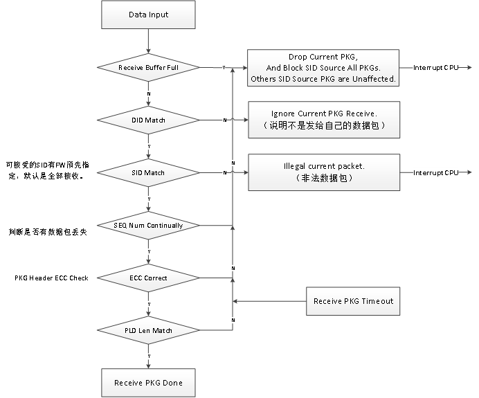
The receiver of module B uses multiple checks to determine the correctness of the data.

Data Receiving Flow
03 Summary
As mentioned above, Dapustor's controllerdesign solution increases the efficiency of transmitting and receiving. It is also possible to improve the data transmission process through simple packetisation of the data.
